Introduction
In my previous posts on BGP filtering, I’ve covered Access Control Lists, Prefix Lists, and AS-Path filters – all focused on controlling which routes are accepted or advertised. But there’s another critical BGP capability that every network engineer needs to master: route aggregation (also called route summarization).
Route aggregation is the practice of combining multiple specific routes into a single, less-specific summary route. This technique serves multiple purposes:
- Reduces routing table size across the internet
- Improves routing stability by hiding network flapping
- Simplifies routing policies with fewer routes to manage
- Conserves bandwidth by reducing BGP update traffic
- Enhances security by hiding internal network details
In this post, I’ll demonstrate BGP route aggregation using the same lab topology from my previous BGP posts, showing you how to create aggregate routes and implement sophisticated policies that advertise different levels of detail to different neighbors.
Understanding BGP Route Aggregation
What is Route Aggregation?
Route aggregation combines multiple contiguous network prefixes into a single, shorter prefix that encompasses all the specific routes. For example:
Individual routes:
  100.1.8.0/24
  100.1.9.0/24
  100.1.10.0/24
  100.1.11.0/24

Aggregated route:
  100.1.8.0/22  (covers 100.1.8.0 through 100.1.11.255)
Instead of advertising four separate /24 networks, you advertise one /22 network that covers all four.
Why Aggregate Routes?
1. Internet Scalability
The global BGP routing table contains over 900,000 routes. Without aggregation, it would be orders of magnitude larger. ISPs and organizations use aggregation to prevent the internet routing table from becoming unmanageable.
2. Routing Stability
When a specific route flaps (goes up and down repeatedly), the flapping is hidden from the internet if only the aggregate is advertised. This improves overall network stability.
3. Security Through Obscurity
Advertising only aggregates hides your internal network topology from the outside world. External networks don’t need to know your internal subnetting scheme.
4. Simplified Policies
Managing policies for one aggregate route is easier than managing policies for hundreds of specific routes.
Aggregation Requirements
For BGP to create an aggregate route, you must have at least one more-specific route from the aggregate range in your BGP table. The aggregate route is created automatically as long as at least one component route exists.
Lab Topology
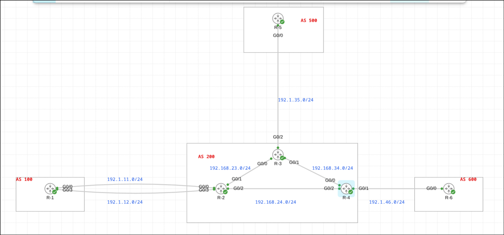
We’re using the familiar topology from my previous BGP filtering posts:
- AS 100: R-1 (edge router)
- AS 200: R-2, R-3, R-4 (iBGP full mesh)
- AS 500: R-5 (connected to R-3)
- AS 600: R-6 (connected to R-4)
For this demonstration, R-2 in AS 200 is advertising four contiguous /24 networks:
- 100.1.8.0/24
- 100.1.9.0/24
- 100.1.10.0/24
- 100.1.11.0/24
Case 1: Basic Route Aggregation
Scenario
R-2 in AS 200 is advertising four contiguous /24 networks to both its eBGP neighbor (R-1 in AS 100) and its iBGP neighbors (R-3 and R-4 in AS 200).
The initial goal is to create an aggregate route that represents all four networks and advertise it alongside the specific routes.
Initial State
Before aggregation, R-2’s BGP table shows the four individual /24 networks:
R-2#sh ip bgp | i 100.1
 *>   100.1.8.0/24     0.0.0.0                  0         32768 i
 *>   100.1.9.0/24     0.0.0.0                  0         32768 i
 *>   100.1.10.0/24    0.0.0.0                  0         32768 i
 *>   100.1.11.0/24    0.0.0.0                  0         32768 i
These routes are being advertised to all BGP neighbors (both eBGP and iBGP).
Calculating the Aggregate
To aggregate these four /24 networks, we need to find the common network that encompasses all of them:
100.1.8.0/24   = 01100100.00000001.00001000.00000000
100.1.9.0/24   = 01100100.00000001.00001001.00000000
100.1.10.0/24  = 01100100.00000001.00001010.00000000
100.1.11.0/24  = 01100100.00000001.00001011.00000000
Looking at the third octet in binary:
- 8 = 00001000
- 9 = 00001001
- 10 = 00001010
- 11 = 00001011
The first 6 bits are common (000010), so our aggregate needs 16 + 8 + 6 = 30 bits… wait, that’s not a standard CIDR boundary.
Let me recalculate properly:
- We have four consecutive /24 networks
- 4 networks = 2² networks
- Therefore, we need a /22 (24 - 2 = 22)
Aggregate route: 100.1.8.0/22
This covers the range 100.1.8.0 through 100.1.11.255.
Configuration
On R-2, create the aggregate route:
router bgp 200
 aggregate-address 100.1.8.0 255.255.252.0
Breaking down the command:
aggregate-address= BGP aggregation command100.1.8.0= Network address of the aggregate255.255.252.0= Subnet mask (/22)
Note: BGP uses standard subnet mask notation, not CIDR notation in the configuration command.
Results
After configuring aggregation, both the aggregate and the specific routes are advertised.
On R-1 (eBGP neighbor in AS 100):
R-1#sh ip route bgp | i 100.1.
B        100.1.8.0/22 [20/0] via 192.168.2.2, 00:01:21
B        100.1.8.0/24 [20/0] via 192.168.2.2, 00:03:45
B        100.1.9.0/24 [20/0] via 192.168.2.2, 00:03:14
B        100.1.10.0/24 [20/0] via 192.168.2.2, 00:03:14
B        100.1.11.0/24 [20/0] via 192.168.2.2, 00:03:14
R-1 now has five routes: the aggregate /22 plus all four specific /24 routes.
On R-3 (iBGP neighbor in AS 200):
R-3#sh ip bgp | i 100.1.
 *>i  100.1.8.0/24     10.2.2.2                 0    100      0 i
 *>i  100.1.8.0/22     10.2.2.2                 0    100      0 i
 *>i  100.1.9.0/24     10.2.2.2                 0    100      0 i
 *>i  100.1.10.0/24    10.2.2.2                 0    100      0 i
 *>i  100.1.11.0/24    10.2.2.2                 0    100      0 i
R-3 also receives both the aggregate and the specific routes.
Understanding Default Behavior
By default, the aggregate-address command:
- Creates the aggregate route in the BGP table
- Advertises both the aggregate and the specific routes to all neighbors
- Continues advertising as long as at least one component route exists
This behavior might seem counterproductive – if the goal is to reduce routing table size, why advertise both? The answer is that BGP gives you control over this behavior, which we’ll explore next.
Key Takeaway
Basic aggregation creates a summary route but doesn’t suppress the specific routes by default. This allows for a gradual transition and gives you flexibility in choosing which neighbors receive which level of detail.
Case 2: Selective Route Advertisement – Different Routes for Different Neighbors
Scenario
Now we have a more sophisticated requirement that’s common in real-world networks:
- iBGP neighbors (R-3, R-4) should receive only the specific /24 routes (for internal routing precision)
- eBGP neighbors (R-1) should receive only the aggregate /22 route (to reduce the global routing table)
This is a best practice: maintain granular routing information internally while presenting a simplified view to the outside world.
The Challenge
We need to:
- Keep the aggregate route advertised to eBGP neighbors
- Suppress the aggregate route to iBGP neighbors
- Suppress the specific routes to eBGP neighbors
- Keep the specific routes advertised to iBGP neighbors
This requires two different prefix lists with different filtering logic.
Solution Architecture
We’ll use prefix lists to control what each neighbor type receives:
For iBGP neighbors (R-3):
- Block the /22 aggregate
- Permit everything else (including the /24 specifics)
For eBGP neighbors (R-1):
- Block the /24 specifics (but only those within the aggregate range)
- Permit the /22 aggregate
- Permit everything else
Configuration – Prefix List for iBGP
First, create a prefix list to filter the aggregate from iBGP neighbors:
ip prefix-list PL-1 deny 100.1.8.0/22
ip prefix-list PL-1 permit 0.0.0.0/0 le 32
Breaking it down:
- Sequence 1:
deny 100.1.8.0/22– Blocks exactly the /22 aggregate - Sequence 2:
permit 0.0.0.0/0 le 32– Permits everything else
This ensures iBGP neighbors only see the specific /24 routes, not the aggregate.
Configuration – Prefix List for eBGP
Next, create a prefix list to filter the specific routes from eBGP neighbors:
ip prefix-list PL-2 deny 100.1.8.0/22 ge 24
ip prefix-list PL-2 permit 0.0.0.0/0 le 32
Breaking it down:
-
Sequence 1:
deny 100.1.8.0/22 ge 24- Matches the 100.1.8.0/22 network
ge 24means “with prefix length greater than or equal to 24”- This blocks 100.1.8.0/24, 100.1.9.0/24, 100.1.10.0/24, 100.1.11.0/24, and anything more specific
- But does NOT block 100.1.8.0/22 itself (it’s not >= 24 in prefix length in the comparison, it’s exactly 22)
-
Sequence 2:
permit 0.0.0.0/0 le 32– Permits everything else (including the /22 aggregate)
Understanding the ge Operator
The ge 24 operator is crucial here. Let’s understand exactly what 100.1.8.0/22 ge 24 matches:
- Matches the network: 100.1.8.0/22 (the aggregate range)
- With prefix lengths: /24, /25, /26, /27, /28, /29, /30, /31, /32
So it matches:
- 100.1.8.0/24 ✓
- 100.1.9.0/24 ✓
- 100.1.10.0/24 ✓
- 100.1.11.0/24 ✓
- 100.1.8.128/25 ✓ (if it existed)
But does NOT match:
- 100.1.8.0/22 ✗ (the aggregate itself – prefix length is 22, not >= 24)
- 100.1.8.0/21 ✗ (less specific)
- 100.1.12.0/24 ✗ (outside the 100.1.8.0/22 range)
This is perfect for our use case: block the specifics, allow the aggregate.
Apply Prefix Lists to Neighbors
Finally, apply the prefix lists to the appropriate neighbors:
router bgp 200
 neighbor 10.3.3.3 prefix-list PL-1 out
 neighbor 192.168.1.1 prefix-list PL-2 out
- R-3 (10.3.3.3) gets PL-1: no aggregate, only specifics
- R-1 (192.168.1.1) gets PL-2: only aggregate, no specifics
Results After Selective Filtering
On R-1 (eBGP neighbor in AS 100) – Only the aggregate:
R-1#sh ip bgp | i 100.1.
 *>   100.1.8.0/22     192.168.2.2              0             0 200 i
Perfect! R-1 only sees the /22 aggregate. The specific /24 routes are hidden.
On R-3 (iBGP neighbor in AS 200) – Only the specifics:
R-3#sh ip bgp | i 100.1.
 *>i  100.1.8.0/24     10.2.2.2                 0    100      0 i
 *>i  100.1.9.0/24     10.2.2.2                 0    100      0 i
 *>i  100.1.10.0/24    10.2.2.2                 0    100      0 i
 *>i  100.1.11.0/24    10.2.2.2                 0    100      0 i
Excellent! R-3 only sees the four specific /24 routes. The aggregate is filtered out.
Key Takeaway
By combining aggregation with selective prefix-list filtering, we achieve the best of both worlds:
- Internal precision: iBGP neighbors have granular routing information for optimal internal path selection
- External simplicity: eBGP neighbors see only the aggregate, reducing the global routing table
This is exactly how large ISPs and enterprises operate their networks.